
Page 6 - e3513a
P. 6
3 Driver
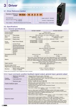
3.1. Driver Reference number
Example of Reference M-EGA - 15 A2 3 01
number :
Driver Model EGA Design number 01:Standard
Maximum output current 15:15 [Arms] Function 3:Pulse train input
Position sensor code 2:Incremental
30:30 [Arms]
Power voltage A:200to230 [VAC] (Single phase/Three phase)
3.2. Specifications
3.3.1. General specifications
Functional item M-EGA-15A2301 M-EGA-30A2301
Control function Position control
Control system IGBT: PWM control Sinusoidal drive
Main circuit Three phase 200 to 230 [VAC] +10/-15 [%] , 50/60 [Hz] ] +/-3 [Hz]
power Single phase
200 to 230 [VAC] +10/-15 [%] , 220 to 230 [VAC] +/-10 [%] ,
50/60 [Hz] +/-3 [Hz] 50/60 [Hz] +/-3 [Hz]
Control power Single phase 200 to 230 [VAC] +10/-15 [%] , 50/60 [Hz] +/-3 [Hz]
Power Main Power (Rated) M-PB1006JN001 : 0.3 [kVA] M-PB3060JN001 : 2.0 [kVA]
capacity Control Power M-PB3015JN001 : 0.5 [kVA]
M-PB3030JN001 : 1.0 [kVA]
40 [VA]
Operating temperatures 0 to 55 [°C]
Storing temperatures -20 to +65 [°C]
Environment Operating/Storing humidity Below 90 [%RH] (No condensation)
Elevation
Below 1,000 [m]
Vibration 4.9 [m/s2]
Shock 19.6 [m/s2]
Dimensions (H×W×D) 160×40×130 [mm] 160×50×130 [mm]
Mass 0.75 [kg] 0.9 [kg]
Alarms Over current, Current detection error, Over load, Regeneration error, Driver overheating,
External overheating, Over voltage, Main circuit power low voltage, Main circuit power
supply open phase, Control power supply low voltage, Encoder error, Over speed, Speed
control error, Speed feedback error, Excessive position, Positioning command pulse error,
Built-in memory error, Parameter error
Digital operator Status display, Monitor display, Alarm display, Parameter setting,
Test operation, Adjustment mode
Dynamic brake circuit Built-in
Regeneration process circuit Built-in *
Monitors Speed monitor (VMON) 2.0 [V] +/-10 [%] (at 1,000 [min-1] )
Torque (TCMON)
2.0 [V] +/-10 [%] (at 100 [%] )
* Please refer 6.Accessories in case of Regenerative reistor is required.
3.3.2. Input command, position feedback signal output, general input, general output
Position Maximum input pulse 5 [Mpps] (CW+CCW pulse, Code + Pulse train)
command frequency 1.25 [Mpps] (90 [°] -phase difference two-phase pulse)
Input pulse form
CW + CCW command pulse, Code + Pulse train command or 90 [°] -phase difference
Electronic gear two-phase pulse train command
N/D (N=1 to 2,097,152, D=1 to 2,097,152)
Position feedback signal however, 1/2,097,152 ≦ N/D ≦ 2,097,152
A/B phase pulse output: N/32,768 (N=1 to 32,767), 1/N (N=1 to 64) or 2/N (N=3 to 64)
Sequence input Z phase pulse output : 80 [count / rev]
Interactive photo coupler (sink, source connection): 6 inputs
Sequence output Line receiver: 2 inputs
Input power voltage range: 5 [VDC] +/- 5 [%] / 12 to 24 [VDC] +/- 10 [%],
100[mA] or over
Servo on, Alarm reset, Torque limit, CW rotation prohibit, CCW rotation prohibit,
Command prohibit,Forced discharge, Emergency stop, Gain switching, Internal speed
setting, Start of estimation of magnetic pole position, etc.
Open collector output: 8 outputs
External power supply voltage (OUT-PWR): 5 [VDC] +/- 5 [%] / 12 to 24 [VDC] +/- 10 [%],
20 [mA] or over
Circuit power for output signal: 5 [VDC] +/- 5 [%] / Max. 10 [mA] (per 1 output )
Circuit power for output signal: 12 to 15 [VDC] +/- 10 [%] / Max. 30 [mA] (per 1 output )
Circuit power for output signal: 24 [VDC] +/- 10 [%] / Max. 50 [mA] (per 1 output )
Servo ready, Power on, Servo on, Torque limiting, Speed limiting, Low speed, Velocity
attainment, Matching speed, Zero speed, Command acceptable, Status of gain switch,
Velocity loop proportional control status, CW Over Travel, CCW Over Travel, Warning,
Alarm code (3 bit), Start of estimation of magnetic pole position, etc.
5